When it came to constructing one of the world’s most advanced category 4 biocontainment facilities, every component of the design needed to fit exactly. David Crampton, Project Director of main contractor, Shepherd Construction, outlines the approach taken to get it right first time.
The Pirbright Institute’s new 11,065m2 laboratory facility in Surrey is set to become one of the most advanced category 4 biocontainment facilities in the world for fundamental and applied research on some of the most devastating viruses of farmed animals.
Before construction began in 2010, we established a close partnership working ethos with the Institute, project team and subcontractors under the banner Team Pirbright to embed a ‘solutions-driven, no compromise’ approach and ensure that the engineering and construction disciplines owned the project jointly.
The laboratory complex, comprising a central hub with north, east and west wings, has a HEPA floor located directly above the first floor laboratory, an air handling floor above the HEPA deck, two basement effluent treatment plants and a stand-alone energy centre.
One of the most exacting requirements has been to achieve a very low air leakage rate of 0.0091 per m3/per m2/hour at +/-200 pascals, a massive 1100 times more compliant than the applicable building regulations at four times the pressure.
To help achieve this, Team Pirbright opted to build not just a mock-up but a full replica of a category 4 laboratory, fully functioning and complete with its own plant space, including HEPA filters, air handling plant and stainless steel ductwork. This, in effect, enabled us to step into the scientists’ shoes, see how the space would be used on a daily basis and test every material, every component and every solution ahead of the construction programme. It was vital that this facility was designed, constructed and tested in advance of the main works to allow lessons learned to be incorporated into the final solution.
Achieving minimal leakage
To achieve the air leakage rates we had to think about a solution for everything that goes through the barrier, whether it is a door, window or service. We also had to consider every eventuality, including how the various chemicals and fumigants that would be in use in the laboratory might affect the materials specified. Therefore it was critical that we understood how the scientists would be using the space and how we could refine on what had been built in the past. The Institute’s team, including two scientists, were fully involved in the process, and have remained so on a daily basis, to provide the support needed by the design and construction team.
Delivering the exacting air leakage rates was made all the more challenging because the design of the main laboratory has aimed to maximise natural daylight through curtain walling and windows rather than resort to a “box-in-box” style space, which has increased the number of penetrations through the barrier.
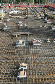
The frame, columns, floors and walls are all concrete rather than a panellised or plasterboard system that would have required jointing and, in-turn, would have led to potential weaknesses.
The frame, columns, floors and walls are concrete rather than panellised or plasterboard to avoid joints that are a potential weakness
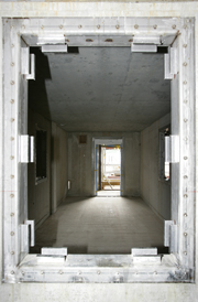
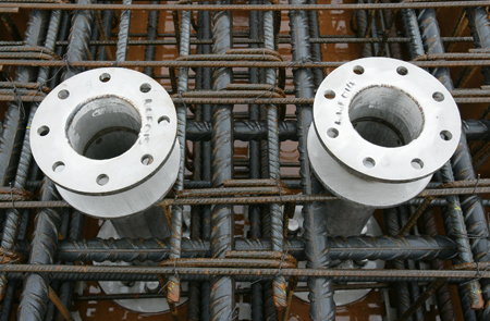
To create the seal around every penetration, including the services, we discounted mastic and instead devised an engineered solution, a series of stainless steel cast-ins that were placed within the concrete and a gasket used to form an airtight seal.
The placement of the cast-ins needed to be identified before construction took place, as drilling holes retrospectively would have compromised the ability to seal the penetration sufficiently.
Initially, building services specialist SES built a 3D model of the facility to challenge the service and plant solutions and confirm the “build before you build” strategy, particularly the need to create a flow of inward air from outside culminating with high negative pressures at the laboratories in precisely-controlled steps. The exact position of every service was then located, even to the extent of how temporary power cabling would be brought into each room or space.
This design was then replicated within the R&D facility and the cast-ins were tested, including their compatibility with the chemicals and fumigants that would be used in the laboratory. The suitability of the concrete with the cast-ins and the containment coatings on the walls was also tested. Once this stage was completed two full-time engineers were employed to precisely locate the position of the 2,200 cast-ins in the actual building and oversee their positioning before the concrete was poured.
To create a seal around each penetration, stainless steel cast-ins were placed in the concrete and a gasket used to form an airtight seal
It was the ability to be able to test the cast-ins and other elements, such as windows and doors in the R&D facility, that gave us the confidence that we could meet the leakage rates. It allowed the company to begin the commissioning process, prove the pressure regimes and carry out cause and effect scenarios well in advance of the main works.
The lessons learned have been recorded and an outputs document produced that we now follow. Fundamentally the R&D facility also helped bring about a change in the ethos of workmanship. This has been critical, particularly as we have been working in completed laboratory spaces where the containment coatings had to be finished before the furniture and service installation commenced.
To ensure the subcontractors know just how important precision and care is in this environment, the R&D facility was used as a classroom backdrop during briefings showing the exact process and sequence to be followed, even down to the type of fixing and drill bit to be used.
The whole supply chain bought into this process, which resulted in the installation teams adopting similar working patterns to the scientists. For instance, an area was created where the subcontractors changed into clean PPE before they entered the laboratory space.
Factory acceptance tests of plant and components have also been critical, enabling components to be tested off-site prior to installation. This includes all the equipment in the stand-alone Energy Centre, which links with both the new laboratory and elements of the existing campus.
The Energy Centre was built early in the programme to give certainty of delivery of all the services to the main laboratory. Through the 3D modelling, SES PRISM was able to fabricate most of the Centre’s equipment off-site, together with the risers, modules and plant skids within the HEPA and plant areas located in the two levels above the main laboratory.
The placement of the cast-ins had to be identified before construction took place
The laboratory plant rooms also contain the air handling units; electrical services including a sophisticated building management system to monitor pressure, humidity and temperature; security and access control.
The laundry, showers and changing rooms are located within the containment space and the intention has been to maximise retention of drainage within this area. Here trenches have been incorporated into the concrete floor that have been coated with the containment coating and will take the effluent down to the two basement effluent treatment plants where it is heat-treated.
Where drainage does leave the contained space, a pipe-in-pipe solution has been implemented with a pressurised gap between the two pipes that is continuously monitored. Any change in pressure triggers an alarm enabling the pipes to be investigated for potential leaks.
By the beginning of 2014, building work and commissioning at Pirbright will have been completed and the client’s validation testing will begin.