The answer is not always straightforward. There are several guidance documents that offer advice on what processes need to be monitored, along with advice on suitable distances from the process being monitored. The goal of this article is to identify the considerations, establish the most suitable location for monitoring a process, and build a scientific rationale for that decision.
Particle counting in pharmaceutical applications can be clearly segregated into one of three categories: certification, qualification and monitoring. Each category requires a different approach.
Certification: Measuring a cleanroom to a standard. The only standard recognised worldwide is ISO14644-1, “Classification of air cleanliness by particle concentration”, which defines how a cleanroom performs and its ability to show uniformity across the entire space. This is done irrespective of the activities performed in it.
Qualification: The process of analysing risk assessment for the activities in the room. Qualification follows grid methodology testing methods. Particle counts are measured in both operational and at-rest states; however, the operational data is the most valid.
Monitoring: The ongoing sampling of the cleanroom on a frequency relative to the degree of control required to prove management over risk to the finished product. The number of sample points and their location is determined by risk assessment, and the qualification and certification processes.
Certification
As mentioned above, cleanroom certification is based on ISO14644-1, “Classification of air cleanliness by particle concentration” standards. The specifics of the assessment may vary slightly for FDA or EU GMP regulations, but the underlying methodology is standard.
Certification demonstrates that the entire area meets a specific ISO classification by particle concentration. That is, irrespective of the final use of the room, only the design and implementation of the filtration system are considered. The international standard means that a cleanroom tested to meet compliance for ISO 5 standards will meet that standard independent of geography and regulatory aspects (i.e. FDA or EU GMP). This provides a universal standard to show that a cleanroom level has been established. Particle Measuring Systems’ products, including the Airnet II and IsoAir 310P Aerosol Particle Sensors, comply with new ISO standards set in 2015. The interactive software of the Lasair III Aerosol Particle Counter can even step the user through the certification process.
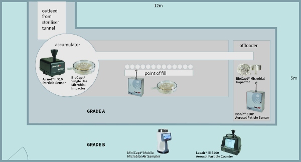
There are many different resources to prove ISO compliance and this article will not cover these in depth. However, using the example of a classic filling machine (Grade A/ISO 5) within a Grade B (ISO 7) background area, the basic rules of testing can be demonstrated.
1. The number of sample points is based on a statistical function of the area:
- Calculate the area of Grade A/ISO5. Find the number of required sample locations in the table.
- Calculate the area of Grade B/ISO7. Find the number of required sample locations in the table.
2. Sample point placement for the Grade A (ISO5) area:
- The sample points must all be equidistant and at work height, irrespective of the activity at the location of their placement.
- Samples are taken in a grid pattern at the identified locations. Derive the minimum number of sampling locations, NL, from ISO 14644-1 Table A.1. This table provides the number of sampling locations related to the area of each cleanroom or clean zone to be classified, and provides at least 95 % confidence that at least 90 % of the cleanroom or clean zone area does not exceed the class limits.
- PASS/FAIL criteria are calculated for ISO and EU GMP Annex 1. It is recommended to have both sets of data, as the FDA requires ISO14644-1, and the EU requires Annex 1 data points (although the EU data would suffice for the FDA).
3. Sample point placement for the Grade B (ISO Class 7) area:
- Repeat the steps used for the Grade A (ISO Class 5) area.
- It may be more difficult to determine the locations of the sample points due to the unusual shape of the room. Derive the minimum number of sampling locations, NL, from ISO 14644-1 Table A.1. This table provides the number of sampling locations related to the area of each cleanroom or clean zone to be classified, and provides at least 95 % confidence that at least 90 % of the cleanroom or clean zone area does not exceed the class limits.
4. A final report is created and marks the end of the certification phase.
Qualification
The qualification phase considers the risks to the quality of the finished product. Each activity must be considered and measured. Continuing with the example of the filling line, let us consider the accumulator table at the exit of the steriliser tunnel. The risk is that glassware (vials/bottles) are exposed to the open environment and operator. Therefore, contamination can fall into clean vials/bottles prior to filling. Operator intervention and the shifting of glassware cause turbulent air movement on the table, impacting contamination risk to the exposed vials/bottles. Therefore, it is an area of contamination risk and the following actions should be taken:
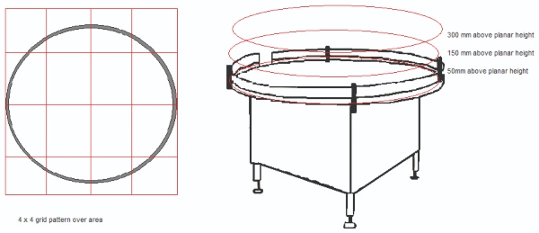
1. Divide the area of risk into a 3x3 or a 4x4 grid. If the activity can occur at several levels, then each level (that is, working height, +150 mm from work height and +300 mm from work height) must be considered.
2. Take a particle sample at the centre of each of the grid squares and on each level.
- Samples are taken during ‘At Rest’ and ‘Operational’ states. It may be required to work around an activity or operator to gain suitable data.
- Slight movement of sample points within the grid square is acceptable. A location is invalid if found to impede normal activities.
3. When all samples are taken this will provide a particle map of the pharmaceutical activity.
Each of the key functions within the cleanroom (filling point, stoppering, general background activities, etc) should be analysed accordingly.
Monitoring
The location of the monitoring points must be based upon a formal risk assessment using tools such as Failure Mode and Effects Analysis (FMEA), Failure Mode, Effects & Criticality Analysis (FMECA), etc, with data from the certification and qualification testing. Other factors, such as equipment interference, mounting points, operator impedance and operator intervention contribute to selecting the final location for the sample probe. In the current regulatory environment, a risk assessment is absolutely required. Without one, poor or incorrect sampling methodology can lead to data unreliably associated with the process or potential impact on finished product quality. Without the option of correlating events, the lack of connection between location and sample frequency can lead to long investigations for out of tolerance events.
There are several steps to defining a risk-based environmental monitoring plan:
1. Process understanding: You must study personnel and material flows within the assessed area in addition to the production operations. This will give an understanding as to how the system is used and what evidence there is to support its state of control, such as:
- Current monitoring practices
- Historical data
- Smoke studies
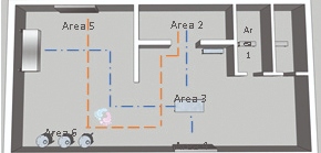
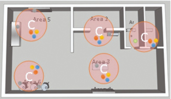
This Gemba walk of the process and rooms is necessary to define the scope of monitoring required and to aid in applying a process that fits with an organization's internal practices. The above figure is an example.
2. Definition of critical areas: Identification using Hazard Analysis Critical Control Point (HACCP) helps which critical areas require environmental monitoring, and identifies areas which meet the needs of a critical sample location.
3. Evaluation of sampling methods: You need to make a determination between traditional methods such as volumetric air samplers, newer technologies such as Rapid Microbiological Methods, or manual collection techniques such as swabbing and contact plates. Also, determine if the chosen method needs to be portable, continuous, remote, etc.
4. Definition of potential sample locations: Determine a single sample location within a critical area, following these criteria (as shown in the adjacent figure):
- Check the available space around the critical area.
- Measure the size of probes and plate holders.
- Determine the accessibility to the location for
operator maintenance. - Assess the interaction between the process operation with personnel and material flows.
- Calculate the probability of potential contamination events.
5. Definition of critical control points (CCP): Each individually considered location is evaluated according to the FEMA method to rank and identify critical sample locations.
6. Define sampling parameters: The sample frequency is found based on the criticality of operations, along with any additional criteria such as incubation parameters, and mitigating measures that might be put into place prior to establishing a monitoring plan.
Sampling practicalities include elements such as the isokinetic sample probe should face into the air stream and the minimum length of tubing should be used. Although different manufacturers claim specific lengths of tubing can be used with their particle counter, this is typically a function of vacuum pump dynamics, and not of particle transportation. Particles of 0.5 μm move freely in long lengths of tubing. However, 5.0 μm particles do not have this same mobility. As 5.0 μm particles are a greater concern, the tubing should be maintained at its shortest recommended lengths1. Particle Measuring Systems quotes maximum tubing lengths based upon the same conditions of airflow, and has a recommended maximum length of 3 m. However, for pharmaceutical particle systems we advise a reduced recommended length of 2 m to ensure transportation of the larger particles.
From the FDA’s Aseptic Processing cGMP Guideline: “Air in the immediate proximity of exposed sterilized containers/closures and filling/closing operations would be of appropriate particle quality when it has a per-cubic-meter particle count of no more than 3520 in a size range of 0.5 μm and larger when counted at representative locations normally not more than 1 foot away from the work site, within the airflow, and during filling/closing operations. This level of air cleanliness is also known as Class 100 (ISO 5).”
The frequency of sampling should reflect the risks and follow from the FDA guidelines on sterile manufacturing and the EU GMP Annex 1. Particle monitoring should be automated and maintained in a continuous state when glassware and products are exposed.