DIN-rail mounting, a small footprint, and a novel method of calibration make the Ashcroft DXLdp well suited to a variety of high-end applications such as HVAC, cleanroom monitoring, biopharm, and biotech applications
The current methods used for in-place diagnostics and calibration verification of low differential pressure transmitters in high-precision or critical airflow systems are very labor intensive and can lead to problems. Agency regulations typically require monitoring and certified calibration on a regular basis. With conventional units, you must periodically remove the pressure tubing and transmitter wires to check calibration against traceable standards.
The patented Si-Glas technology ensures long-term stability, high performance, and reliability, while the DXLdp’s specially designed valve actuator allows you to quickly redirect the process without having to remove the process lines.
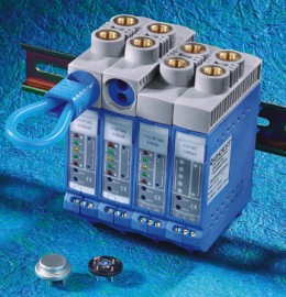
This novel approach does not translate into a larger unit—quite the opposite, in fact. The DXLdp maintains a small footprint by mounting on DIN rails (see Figure 1). Besides making transmitter installation and system expansion easier, rail mounting reduces the DXLdp’s required footprint area by a factor of four compared with other transmitters.
An additional advantage is that mounting screws are required only for the DIN rail and not for each transmitter. This means smaller and less costly cabinets for the same number of transmitters (see Figure 2), reducing installations costs. The DXLdp is designed to snap onto the DIN rail and is easily removed without additional tools.
Spinning the SpoolCal
The DXLdp can be configured with options to allow greater user flexibility. Most important is the SpoolCal actuator valve option (see Figure 3). This clever valve has two positions: CALIBRATE and MONITOR. In CALIBRATE, the transmitter sensor is isolated from the process and allows externally generated test pressure input for calibration. In MONITOR mode, the valve provides online, uninterrupted output of the process pressure without physically disconnecting the process tubing.
In either mode, the pressure can be monitored or recorded with pressure measurement equipment such as a hand-held calibrator, as shown in Figure 2. In both modes, online access to the actual electrical output is available through test jacks on the front panel of the DXLdp.
Straightforward operation
To verify a DXLdp calibration, simply insert the SpoolCal valve actuator probe, referencing high and low pressure. A 90° clockwise rotation isolates the internal sensor from the process pressure. This allows external pressure input through the probe. Shorting the probe’s high and low ports provides a quick and accurate zero differential pressure. Additional calibration points can be generated with an external UKAS-traceable pressure source. The ZERO and SPAN adjustments, located on the front panel, are non-interactive.
To activate the monitor mode and make online pressure and electrical signal measurements, simply rotate the probe 90° counterclockwise. This is the process pressure both to the DXLdp sensor and out through the probe tubing to a pressure-measuring device. You can therefore monitor or record an online pressure and electrical signal at the transmitter location without taking the system off line.
Additional options
Developed for high-reliability and high-precision pressure and flow control in biotech and pharmaceutical applications, the DXLdp is also well suited for demanding HVAC building applications and fab plant air monitoring systems with the requisite pollution control. Common to all these applications is the need for easy access to status information and convenient adjustment of the transmitter. Three additional options address these needs.
LED Display provides quick diagnostic information. The display’s range status indicators are especially useful in cases where diverters or fans have failed, or blocked intakes drive the pressure beyond the design range of the system. An amber zero LED indicates little or no differential pressure. Two red LEDs highlight either an overpressure or an underpressure condition. Green LEDs show that the pressure is in the operational range of the transmitters, either bidirectional or unidirectional.
Front Access Test Jacks provide convenient, snap-in connections for online output signals without having to remove wiring on current loop controlling units. You can then measure the electrical output with a standard multimeter or data-collecting instrument such as the Ashcroft ATE handheld calibrator.
2:1 Turndown lets you rescale the units – in the field – to one-half the upper range pressure limit via a jumper accessed through a window on the side of the unit. For example, a 100mbar unit with 4–20 mA output could be adjusted to 50 mbar while maintaining the same output.
The DXLdp is available in 0.25%, 0.5%, and 1.0% terminal point accuracies. Both unidirectional and bidirectional pressure ranges are available with a wide selection of outputs, including 4–20 mA and 1–5, 1–6, 0–5, and 0–10 VDC. The front instrument panel zero and span adjustments are noninteractive, making field calibration and adjustments easy. The DXLdp has been tested and CE certified to exceed radiated and conducted immunity in heavy industrial applications. Additional performance options are available, including adjustable signal response time and custom ranges.
Summary
DIN-rail mounting makes for compact, less expensive and more flexible installations. Local LED range-status indication lets you quickly diagnose control problems at system start-up or when troubleshooting. Turndown allows more output signal when unexpected, lower pressures occur. Best of all, the SpoolCal feature addresses one of the most problematic issues with low differential pressure transmitters: convenient access to pressure and electrical signals. An automated airflow system can now continue to process the transmitter’s signal and at the same time let you monitor or record at the transmitter location while the system operates. All this helps improve system reliability and reduces downtime – a welcome combination for designers, fabricators, installers, and maintenance personnel working on critical and demanding high-end applications.


