Airborne particle counters are widely used to monitor for signs of cleanroom air contamination and, in most cases, the particle count data is used to make critical process decisions. Today’s portable particle counters have come a long way with the advent of laser diode technology, so the older generation cumbersome helium-neon lasers have been phased out in favour of smaller, lighter and feature-packed new technology. New touchscreens devices, which can deliver automatic certification reports that comply to many of today’s cleanroom certification standards, need to be validated to ensure they meet process requirements. With so much focus on data integrity and the FDA’s ALCOA approach, it is crucial to understand particle counter technology to assist decision makers when considering which option/model is best for a process when data integrity is paramount.
Critical parameters
Particle counters measure what we cannot see. To get some perspective, a 0.5 µm particle is about 200 times smaller than the diameter of a strand of your hair.
To count particles laser light is used to reflect light from the particles as they pass through the laser beam. Airborne particle counters using laser diode technology count particles by collecting scattered light inside the sensor of the particle counter (see diagram).
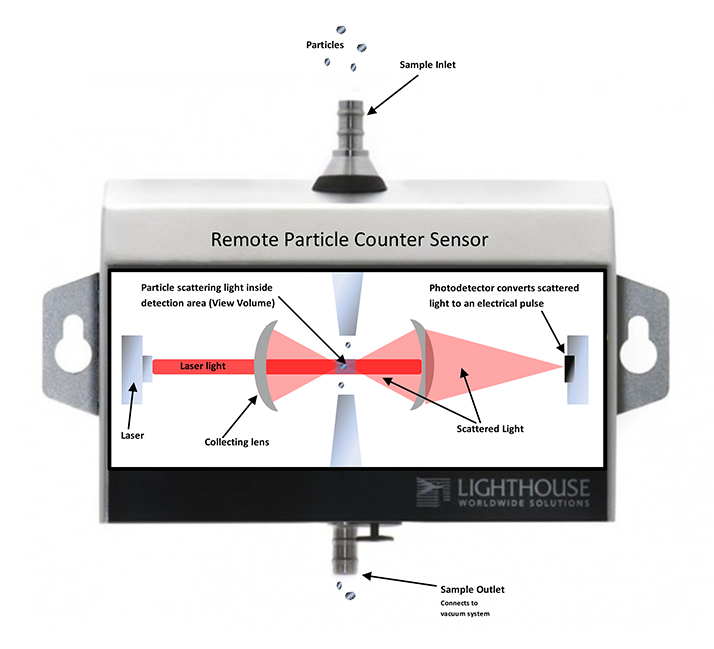
Diagram: Airborne particle counters using laser diode technology count particles by collecting scattered light inside the sensor of the particle counter
The scattered light occurs when a particle goes through the “view volume” of the sensor. The view volume is the target location in the sensor where the laser beam and the flow path converge.
The laser light generated from the laser diode crosses the view volume and particles are directed through the view volume by an internal air pump. The flow rate of the internal pump is controlled by a feedback loop and a mass flow controller, which keeps the flow rate constant.
When choosing a portable particle counter there are few options to consider when it comes to flow rate. The options are typically a cubic feet per minute (1CFM), 50l/min and 100l/min. A 1CFM flow rate will pull a 1m³ volume of air in under 36 minutes. A 50l/min flow rate will take 20 minutes, and a 100l/min flow rate will take 10 minutes to sample a 1 m³ volume of air.
The particle counter sensor is tuned into the flow rate so sample flow plays a critical role in the accuracy of the particle sizing. If the flow is too slow the particle dwells longer in the view volume, scatters more light and is perceived as a large particle than it actually is. If the flow rate is higher than nominal flow then the particle dwell time in the view volume is less and the light energy picked up by the photodetector is less than normal hence the particle is perceived as a smaller particle than it actually is.
Streetlights that magically switch on when it gets dark at night and switch off in the morning when it gets light are triggered by photodetectors. The photodetectors change in resistivity based on light intensity or lack of is used to trigger the on/off switch for the street light. The photodetector inside a particle counter sensor is more advanced and basically converts the scattered laser light into electrical energy in the millivolt (mV) range. The amount of light scattered is proportional to the size of the particle.
Routine testing
Big particles scatter more light than small particles. This is the fundamental conversion of a physical particle into electrical energy that can be measured. Once measured the mV signal is captured then threshold comparators size the particle and the sized particles fall into different size ranges, which are displayed on the particle counter as count data at different sizes. If the flow rate is not within specified tolerance then sizing errors can occur.
If the laser light is not running at its optimum intensity then there is an accuracy error factor that comes into play. Laser health should be monitored consistently and error signals communicated if laser levels drop below optimum ranges. If the laser is not illuminated at its nominal working range then there is the possibility of some small particles passing through the view volume undetected.
Laser alignment is also a critical factor. If the laser is not aligned correctly then the particle count accuracy will be wrong as missalignment will also have the same effect of missing particles and the overall result will be inaccurate particle counts. The photodetector converts the scattered light as photons into electrical pulses by creating a charge for each received photon.
As the amount of scattered light increases with the particle’s size and the scattered photons arrive at the same time, a current pulse proportional to the particle’s size is generated.
If a photodetector is defective, some less technologically advanced particle counters will continue reporting zero counts and no scattered light will be picked up therefore no counts will be registered. Even if airborne particles are present they will go through the particle counter sensor undetected. In normal cleanroom environments reporting of zero counts for several hours is not uncommon.
There is a false sense of security if the photodetector is not monitored; using a particle counter with advanced technology that monitors the photodetectors health mitigates from false zero counts. This issue is difficult to detect especially when you expect to see zero counts. Routine testing can detect if a photodetector is faulty if the particle counter does not signal an error to the user.
One of the biggest problems with particle counter data integrity occurs when contamination builds up around the sensors optics and mirrors. This normally happens during cleaning operations when the inlet is not capped, causing cleaning solution to coat the optics, which causes the sensor to fail calibration. If you are on annual calibrations and there is a calibration failure, then how confident are you in your data for the last 12 months?
A particle counter that monitors sensor health is a good choice and assists in sending out service notifications when background contamination becomes an issue. These advanced instruments can mitigate failed calibrations and assist in maintaining data integrity. These sensors can be pulled from service, tested and recalibrated before failed calibration issues could potentially ground your batches.
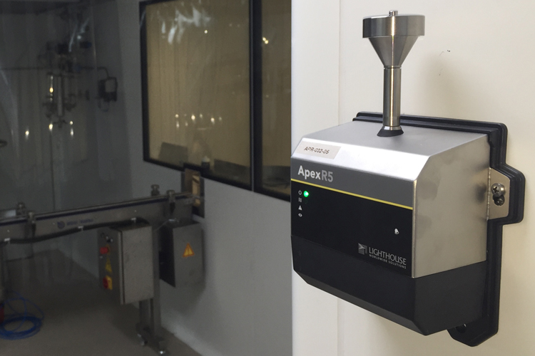
Location identification is crucial. If data coming from the sensor is picked up from the wrong location, a small mistake can have a huge impact and lead to major data integrity issues. Look for remote particle counters with technology where the location ID is embedded in the location mounting bracket rather than the particle counter. This way, any remote particle counter can be inserted and the data will be confirmed from the right location 100% of the time.
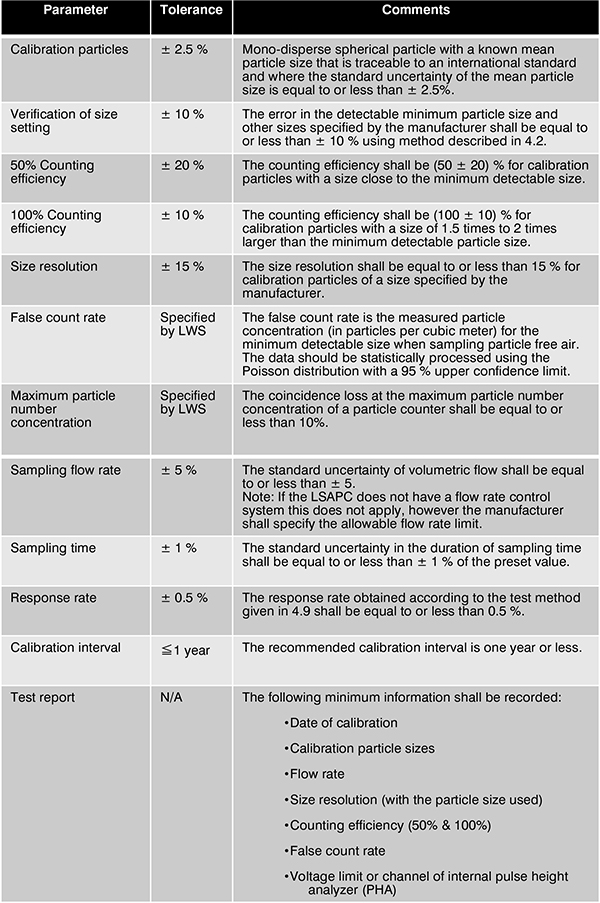
Critical test parameters of ISO 21501-4 The table above defines the parameters of ISO 21501-4
Calibration and data integrity
Particle counter data plays a critical role in the product life cycle. By selecting the right equipment and services you can mitigate these risks and have more reliable data from a validated source. The data from your particle counter must be reliable, accurate and from a source without manipulation.
Data integrity refers to the completeness, consistency, and accuracy of data. The data should be attributable, legible, contemporaneously recorded, original or a true copy and accurate (ALCOA).
Although ALCOA has been around for many years it has now taken on a phoenix-like resurgence and every man and his dog is talking about it. But data integrity is nothing new. It has been the expectation in PIC’s Guide to GMP, Chapter 4 and Annex 11, ISO 13485: Sections 4.2.3, 4.2.4, as well as the Australian Code to GMP human blood, blood components, human tissues and human cellular therapy products: Sections 400-415.
To follow the ALCOA standard, an audit trail built into the equipment or software is an absolute must. Seek particle counter technology with built in audit trails to satisfy ALCOA requirements for who, when, what and where events.
The system must conform to 21CFR11 guidelines. Up to three security levels from operator to manager and administrator must be available with the usual compliant parameters such as password length, password ageing and password control. User security levels are a 21CFR11 requirement and particle counters should have the ability to manage and control user access.
A complete validation of the data records must be conducted by verifying the accuracy of the data to the location of where the data is generated. This is a must-do exercise and should be rolled into the installation and operational qualifications IQ/OQ protocols. Seek vendor IQ/OQ protocols and always conduct a performance qualification (PQ) to verify operational accuracy before going into production.
ISO 21501-4 has been around for 10 years and the recent update to ISO 14644-1:2105 (cleanrooms and associated controlled environments – Part 1: Classification of air cleanliness by particle concentration) requires airborne particle counter calibrations to be completed following ISO 21501-4 (see table on p33).
Particle counters are critical in today’s cleanrooms. Mitigating data integrity issues on particle count data comes by really understanding how particle counters operate and the critical parameters that need to be tested and maintained.
Knowledge of particle counter technology at this level helps the end user understand the importance of properly maintaining the instrument so the data supplied by the particle counter is reliable and accurate.
There are many parameters to consider that effect particle counter accuracy. Lasers are sensitive to heavy handling and major vibrations as the laser alignment could be affected.
Contamination of the sensor is also a major problem and a sensor with built in sensor health checks is the best option in mitigating data integrity issues.
Proper training and internal SOPs should be developed and maintained to support good housekeeping.
Knowledge of particle counter technology helps the end user understand the importance of properly maintaining the instrument
Mitigate the risks
Regular maintenance and calibration programmes are highly recommended along with more regular tests to verify the sensor is functioning normally. Using zero count filters and monitoring sensor health is a big step in the right direction to further mitigating data issues.
Annual calibration is good practice to confirm the instrument has been in tolerance but more frequent calibrations should be considered if the instruments data is critical to your process. For example, most remote particle counter users calibrate their sensors more frequently as the data is used to support batch releases. Therefore, it is critical that the calibration data indicates that as founds are within tolerance.
ISO 21501-4 plays a major role in particle counter calibration to ensure repeatability and accuracy. Validation of the particle counter onsite also adds a level of confidence that the particle counter operates correctly.
Overall particle counters play a vital role in monitoring the air quality of your cleanroom and manufacturing process. It is important to understand the technology and to use this knowledge to developing strong environmental monitoring programmes for certification and routine monitoring. Choosing the best technology has it is advantages and helps to mitigate risks in your process.


