How-to guide: Pass box qualification

Published: 26-Feb-2019

Material transfer equipment plays an important role in minimising contamination risks during the manufacturing process. Industry expert, Jesus Casas, gives an overview of available pass boxes and a step-by-step explanation on how to qualify them appropriately

Those who work in cleanrooms know it well: avoiding cross-contamination between rooms with incompatible cleanroom classifications is essential to preserve the desired ISO classification and maintain the integrity of products and processes. One way to achieve this is by minimising material movement.

Non-viable particles and microorganisms can cause contamination in a cleanroom due to this entry and exit of materials within the controlled environments. With this in mind, it is necessary to design and correctly install material transfer equipment.

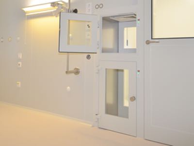
A pass box, which is also called a transfer hatch or SAS pass (sterile access system), works as a barrier between areas with different levels of cleanliness when materials do have to be moved. The equipment is used to transfer material from an area of lower cleanliness to an area of higher cleanliness, and vice versa.

All cleanroom pass boxes include a mechanical and/or electrical interlock system designed to minimise the risk of cross-contamination. This design ensures that only one door can be opened at a time, not both or more, thus minimising the amount of “dirty” air that can enter the cleanroom.

How-to guide: Pass box qualification

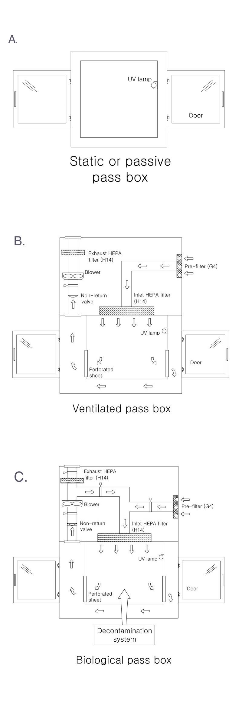
Usually, pass boxes have a UV light lamp in them to remove the contamination that may enter during the transfer of material.

Three types of pass boxes are used in the pharmaceutical industry, these are:

  • Static or passive: designed for the transfer of materials between areas with the same cleanliness class, without a filtration system. The system still uses interlocked doors during the changeover, allowing for the removal of material from the other door so as not to contaminate the clean area. The product in transfer is also still subjected to a controlled time of UV light radiation. See figure A.
  • Ventilated: designed for the transfer of materials between classified areas or between a classified area and a non-classified area, with decontamination through air sweeping HEPA filters. The unit is equipped with a ventilation system coupled with air filtration to ensure a clean environment inside the chamber before the opening of the door. See figure B.
  • Biological: for the transfer of materials for biological neutralisation of elements and bio-contaminated materials between classified areas, or a classified and a non-classified area. The unit is equipped with a bio-decontamination system through filtered air and disinfection using hydrogen peroxide generator (external or integrated). See figure C.

Quality assurance

The qualification of pass boxes in the pharmaceutical industry is a quality assurance process, which involves documented evidence of consistency that the equipment works according to its purpose.

There is not a standard that defines the methodology to qualify a pass box, but it is possible to adopt the principles given in ISO 14644 and other standards because these boxes work much the same as a unidirectional airflow device.

With this in mind, an airflow velocity test is required. The purpose of this test is to document the average airflow velocity within the pass box.

The measurement range must be a cross-sectional area of the filter face perpendicular to the airflow. When using a single point measurement instrument, such as a hot wire anemometer, divide the filter face into a grid of equal sections, no greater than 0.09 m2 (see Figure 1).

Figure 1. Grids pattern for velocity measurements, using a hot wire anemometer. The points in the centre of each grid represent a point for velocity measurement, the anemometer should be placed on that point

Figure 1. Grids pattern for velocity measurements, using a hot wire anemometer. The points in the centre of each grid represent a point for velocity measurement, the anemometer should be placed on that point

When using a multi-point instrument, such as vel-grid, make the sections no greater than 0.37 m2. Measure the airflow velocity at each grid point, 150 mm from the filter face, or from the protective grille over the filter. The average airflow velocity should be 0.45 m/s +/- 20%.

Equally, an airflow visualisation test should be performed. The purpose of this test is to show the actual airflow pattern throughout the pass box. It can also be used to demonstrate the effects on airflow caused by equipment or “as used” condition.

The airflow visualisation test is done using non-contaminating items such as visible vapour source or streamers of thread or string.

When ready to perform the test, place the output of the smoke source 150 mm from the filter face or the protective grille. Then disperse the smoke over the entire filter face and carefully observe the airflow displacement into the pass box. Smoke should also be released along the work surface. The smoke should flow smoothly, drawn from the release point towards the slots in the bottom or the sides of the pass box.

While conducting “as used” tests, release the smoke around the equipment inside the pass box. During the test, any lazy airflow observed may be caused by the equipment.

Testing the integrity of HEPA filters is yet another step involved in the qualification process. This test is performed to confirm that the filter system is free of leaks. The test is performed by introducing an aerosol challenge upstream of the filter and scanning downstream to detect leaks.

The aerosol is fed into the air supplied to the filter in a manner that will produce a uniform challenge concentration at each of the filters being exposed at the same time. The filter face and the perimeter of the filter assembly must be scanned by passing the probe in slightly overlapping strokes so that the entire area of the filter is sampled. The probe should be held approximately 25 mm from the filter face and any aerosol photometer leaks should not have a penetration greater than 0.01%.

Like this story? Subscribe to Cleanroom Technology magazine for incisive analysis of the latest news and developments in hi-tech industries manufacturing in controlled environments.

Inspections are also performed to determine the actual particle concentration within the pass box at the time of a test. In this case, place the particle counter in the centre of the pass box work surface. Turn on the particle counter and measure the concentration of particles. The minimum sample volume should be 1 m3. The air inside the equipment must have met the acceptance criteria for an airborne particulate cleanliness class for a grade A. See Table 1, for the specification of a grade A class of cleanliness.

How-to guide: Pass box qualification

Recovery Test

The ability of a pass box to return to its specified cleanliness class after being exposed to contamination should, and can, be determined, with a recovery test.

Two methods are available for this purpose. The first is described in the standard ISO 14644-3. The document recommends sampling at the centre of the work area or a specific area where work may be performed. First, the particle count should be measured to establish the existing particle concentration level.

The next step is to generate a particle challenge, normally an aerosol, to 100 times more than the desired cleanliness level. As soon as the challenge has been triggered, record the start time, and begin concentration measurements. Finally, the challenge concentration should be taken for a six-second period every minute, until the unit tested has returned to the original particulate concentration.

The second method assumes a clean air supply, with a concentration of 0, so the recovery time can be calculated according to an equation. The following is a simplified model for calculating the relationship between the air change rate and recovery period. This model is based on the assumption of good mixing efficiency with clean supply air.

How-to guide: Pass box qualification

Where:

Crrest: final room concentration
Crop: initial room concentration
Cs: supply air concentration.
(assuming a clean supply air, Cs = 0)

N: room air change rate
t: time (hours)

Annex 1 of the European GMP guidance refers to a typical recovery time of 15–20 minutes from operational particulate levels to at-rest particulate levels. But this is normally associated with 20 air changes rate per hour. Due to the smaller size and subsequent greater air changes rates in a pass box, however, this time frame should be shorter.

For example, a 100-fold recovery, from ISO Class 7 to ISO Class 5, with 240 air changes per hour (typical air change rate in an ISO Class 5 class) would take approximately a minute. Figure 2 shows that by assuming a simple exponential decay the “recovery period” changes greatly with air change rate.

Figure 2. Recovery period versus air change rates <br> (ISPE Baseline Guide Volume 3: Sterile Product Manufacturing Facilities)

Figure 2. Recovery period versus air change rates
(ISPE Baseline Guide Volume 3: Sterile Product Manufacturing Facilities)

If the equipment has a timer, it should be adjusted accordingly to the recovery time determined.

Microbiological challenge

The UV efficiency of a pass box is tested using the microbiological challenge test, which is carried out simulating exactly the real operative condition. For this test Bacillus subtilis is usually used as a challenge microorganism.

Basically, this test consists of the exposure of Petri dishes with culture medium, which is inoculated with a certain concentration of Bacillus subtilis. These plates are then exposed to UV radiation for the time determined by a validation study of UV inactivation.

The expert advice is to follow each of these tests to assess the qualification of pass boxes. It is the only way to ensure the risk-free transfer of material from lower level cleanroom areas to higher ones, under current cleanroom regulations.

Moreover, the qualification process may lead to a deeper understanding of the equipment involved.

About the author
Jesus Casas is a mechanical engineer based in Caracas, Venezuela. His career spans more than five years of experience in the pharmaceutical sector. Casas specialises in the areas of validation, qualification and metrology.

N.B. This article is featured in the March 2019 issue of Cleanroom Technology. The digital edition is available online.

You may also like