The most demanding manufacturing process in terms of cleanliness and environmental control is wafer processing – the manufacture of semi-conductor devices in the semiconductor front-end industry. The process is carried out in isolated cleanroom environments in which humidity, temperature and particle contamination are monitored and controlled within specified parameters.2
Some processes require ultra-clean environments, due to the submicron feature size of modern semiconductor devices. The size of contaminating particles ranges from less than 10nm to more than 100µm, and the particles are either suspended in a gas or attached to a surface.
Both contamination types must be limited per a given specification, depending on the process. Air cleanliness classes are defined in ISO 14644-1, which specifies upper contamination limits per class. The ISO reference particle diameter of 0.1µm offers a denomination scheme with simple, single-digit class numbers that correspond to the obsolete standard FED 209E. The critical particle size that poses a risk to a device is roughly half of the device’s critical dimension.
It is generally difficult to maintain the required cleanroom conditions with human operators, and automation systems with moving parts are also contamination sources. One motivation for highly automated fabs is the replacement of humans with robots and other automation systems from cleanroom areas.
The primary technical challenge is how to minimise the number of particles generated by robots and provide damage-free handling of wafers and other substrates.
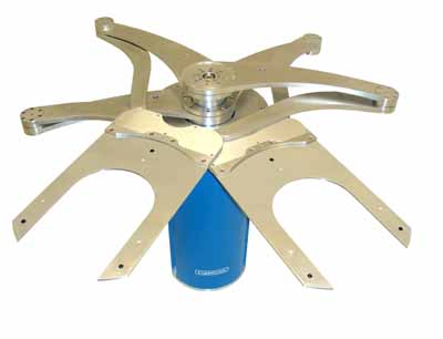
In this article the design guidelines for two categories of substrate-handling cleanroom robots are addressed: atmospheric robots, which operate at the ambient atmospheric pressure; and vacuum robots, which operate in extremely clean enclosures, either in vacuum or certain gas environments. The predominant robot type employs a SCARA-type kinematic structure with one vertical axis of motion, and a 2-link arm with an end-effector that moves in a horizontal plane (see Fig. 1).1
Atmospheric robots
Design guidelines for atmospheric cleanroom robots address several aspects, including suitable materials, clean drive trains and surface finishes. Specific materials are chosen for cleanroom robots that will reduce particle contamination from contact, friction and out-gassing. These include materials for parts and components, coatings, lubricants and material surfaces.
Suitable materials include stainless steel, aluminium, some plastics, composites and ceramics. Stainless steel is generally used for critical moving parts (bearings, lead screws, etc.) and small parts (screws, washers, etc.), as well as parts that are exposed to vacuum or aggressive environments.
Flexing parts — a common source of particle contamination — and parts that make contact with substrates, are made of suitable plastics or composites, such as PEEK, PFA and PTFE.
Non-metallic materials are recommended for contacting substrates. Desirable mechanical, electrical and thermal properties for structural robot components (including arm links, the robot base and end-effectors) are: good cleanliness, stiffness, durability, and good resistance against wear, heat, and corrosion in aggressive environments. Aluminium alloys are often used for structural components. Ceramics can be used for end-effectors, although the high cost limits their use despite the desirable properties. Conductive ceramics are available to prevent electrostatic discharges .
The use of cleanroom-compliant lubricants is important. These synthetic materials are chemically stable and non-toxic and have a low vapour pressure that minimises particle generation and outgassing. Several commercial products are available.
The robot drive train is the set of moving parts and components that transforms primary energy into kinetic energy and delivers it to the robot’s interface with the outside world.1 Common drive trains comprise electric motors, transmissions (e.g. lead screw), belts and pulleys, linear and rotary bearings and mechanical parts.
SCARA-type substrate-handling robots in semiconductor manufacturing employ at least three axes of motion: the radial arm axis, the robot rotation axis and the vertical Z-axis (Fig. 1). Each axis of motion has its own drive train with the main components.
The internal drive trains generate particles during motion. The particles exit the robot base through gaps and openings if the internal pressure exceeds the ambient air pressure. This is the case, for example, when the Z-axis assembly retracts into the base (negative Z-motion). Particles are ‘pumped out’ of the robot base by the displaced air. The air exits the robot base through any available openings, particularly through the gap between the Z-axis assembly and the top of the robot base. The latter occurs in the vicinity of the substrate and poses a substantial risk to product yield.
This effect can be avoided by creating an internal air pressure that is slightly below the ambient atmospheric pressure, e.g. with a small fan integrated in the robot bottom plate. The contaminated air and any airborne particles exit the robot base through the bottom plate, providing the maximum possible distance to the substrate on the end-effector.
Basic guidelines for designing clean drive trains include:
- All moving parts are below the substrate (no particles fall onto the substrate)
- Minimise the number of moving parts
- Evacuate generated particles
- Select abrasion-resistant and wear-resistant materials
- Use a suitable belt/pulley alignment and belt tension for belts and pulley drives
- Consider direct drive joints to avoid contaminating mechanism, if possible
- Apply only non-volatile lubricants and follow strict procedures
- Encapsulate bearings
External surface finishes of cleanroom robots must not generate particles or vapour. This is achieved with inherently clean materials and smooth surface finishes that protect against corrosion. Any interruption of a smooth surface, including holes, slots and crevices, can collect and later release particles. Therefore all interior and exterior corners should have larger than usual fillets and radii.3 Polished exterior finishes are optimal and recommended materials include stainless steel, painted steel and anodised aluminium. Elastomeric urethane, urethane enamels and epoxy enamels are preferred for painted surfaces. All surfaces should demonstrate 106 to 109 Ohm/sq resistivity4 to prevent the build-up of electrostatic charges. This can be achieved with suitable metals, but also with conductive surface treatments (nickel-plating) and conductive powder coats.
Vacuum robots
Some semiconductor manufacturing processes require an ultra-clean vacuum environment or a controlled environment of a gas mixture and there are guidelines specific to the design of vacuum robots.1
Vacuum pressures used in electronics manufacturing range from low to ultra-high vacuum. Vacuum robots are typically mounted at the centre of a vacuum cluster tool (VCT) (Fig. 2). The design objective for these robots is to provide the specified cleanliness and vacuum integrity in a VCT. The main robot design challenges for high and ultra-high vacuum include:
- Static vacuum barrier that separates the vacuum and atmosphere environments
- Dynamic vacuum barrier that transfers motion from atmosphere into vacuum
- Prevention of external and virtual leaks that limit the achievable vacuum pressure in the chamber
- Minimising the use of materials that outgas at or above the specified vacuum pressure
The static vacuum barrier separates the vacuum environment from the atmospheric environment. It does not include moving parts and does not transfer motion from atmosphere into vacuum. A static vacuum barrier is usually a seal that comprises three main components: two opposing metal flanges, bolts or clamps that press the flanges together, and a gasket between the flanges.
The design of these components depends on the application. The barrier must withstand the specified maximum pressure and also endure the pressure changes that result from loading and unloading the process tool. Reusable plastic gaskets can be used for low vacuum; single-use copper gaskets are needed for high vacuum.
Vacuum robots in semiconductor manufacturing operate only partially in vacuum: the robot arm is in vacuum, while the robot base resides in ambient atmosphere. Motion generated by motors in the robot base is transferred across a dynamic vacuum barrier into vacuum to control the arm. The barrier provides the required vacuum integrity. Technologies include: magnetic feedthroughs, bellows, magnetic couplings, motors with integrated vacuum barrier, harmonic drives and lip seals. These barrier technologies are suitable for rotary joints. Bellows and lip seals can also be used for prismatic joints. The cost of dynamic vacuum barriers can be significant, depending on the specified vacuum pressure and the number of axes of motion transferred into vacuum.
Vacuum-compliant lubricants are critical for high and ultra-high vacuum applications. These synthetic materials are chemically stable and non-toxic with a low vapour pressure and low outgassing. Three common lubricants are hydrocarbon, silicone, and PTFE-based perfluorinated materials. Their compatibility with a given process or tool materials must be assured.
In conclusion, the design challenge associated with cleanroom robots is the compatibility with demanding cleanroom requirements that are unknown in most other industries. By following the discussed design guidelines for atmospheric and vacuum robots, the required cleanliness for a given process, in either atmosphere or vacuum, can be achieved.
References1. Mathia, K. (2010). Robotics for Electronics Manufacturing - Principles and Applications in Cleanroom Automation. Cambridge: Cambridge University Press.
2. SEMI E49.6-1103, Guide for subsystem assembly and testing procedures - stainless steel systems.3. International Sematech (1992). Sematech standard 92051107A-STD, Guide to Contamination Control in Design, Assembly, and Delivery of Semiconductor Equipment, Austin, Texas (1992).
4. ANSI/ESD STM11.11-2006, Surface Resistance Measurement of Static Dissipative Planar Materials.


